This white paper looks at using mental ray® software for architectural visualization.
Autodesk® 3ds Max® 9 software includes many major feature and workflow improvements
to reduce complexity and make rendering with mental ray far more approachable
for Architects and designers.
This document summarizes the important aspects of photorealistic renderings that
Architects, designers and visualization professionals may want to consider when creating
presentation images, visualizations for design review, or physical analysis of lighting. It
identifies the main areas involved in physically based renderings and provides guidance
as well as tips-and-tricks on how to use them in 3ds Max. The main areas of focus
include:
1.Lighting and materials theory
2. mental ray renderer
3. The mental ray daylight system
4. Arch+Design material for mental ray, and more
Included with this document are sample scene files and renders to help provide context.
Transforming Digital Painting into Digital Photography
In the real world, energy is emitted by light sources, bounces around, and is absorbed by
surfaces. The same principles apply in global illumination rendering, especially in architectural
visualization. Architects, Designers and Visualization Professionals need be able
to render images that approximate the real world as closely as possible. In combination
with structure and surfaces, light can change the appearance of a room tremendously.
Setting up the Workbench
Profile Presets
3ds Max software ships with a tool that enables you to preset
environmental defaults that suit the workflow of photorealistic
renderings done with mental ray. This is a great place to start.
By choosing the ‘Design VIZ/mental ray’ profile, you get the following:
1 ray renderer
2 Exposure control
3 New mental ray ‘Arch+Design’ material in the ‘Material Editor’
4 New ‘mr Sun’ and ‘mr Sky’ plug-ins in the daylight system
5 that cast shadows and are set to be ray-traced
Units and Scale
Physically based lighting computation implies that light attenuates
using the inverse square falloff law, which simply means
the intensity of light declines exponentially with the distance it
travels. Therefore, it is crucial that the scale of your scene corresponds
to real-world data—otherwise the results will get corrupted.
A common mistake is to import an airport at the size of a shoebox
or a room at the size of a stadium. In one case, the lighting
computation will be too bright, and in the other case, it will be
too dark.
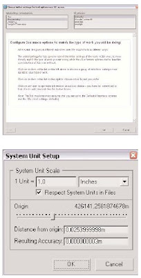
To verify your scale settings, check the ‘System Unit Scale’ settings
in the ‘Customize | Units Setup | System Unit Setup dialog
box’:
You may also want to use the ‘Tools | Measure Distance’ tool to
verify known dimensions in the scene, as well as set the ‘Unit
Conversion’ function in the Import menu when, for example,
importing a DWG™ file from AutoCAD® software.
Optimizing Geometry for Rendering
Good renderings require good geometry. Good geometry does not mean you must model
everything. You can obtain many detailed effects with optimizations such as bump maps
or cutout maps. It only means that the geometry must correspond roughly to what the
renderer expects. It is important to start with a clean model. Fortunately, mental ray is
more tolerant than radiosity in this respect; you do not have to create perfect models, but
more accurate models make rendering easier and more efficient. The following sections
describe good practices for optimizing geometry before rendering.
Smoothing Angles
All 3D geometry—including both edged objects and rounded forms—is made up of polygons.
To display them smoothly, 3ds Max interpolates between the surface normals to
simulate a rounded form and not a faceted one. When importing a file from another computer-
aided design (CAD) or 3D application or when working with the Edit Poly modifier,
you may find that the information about which normals to smooth by interpolation and
which to keep sharp edged with no interpolation can sometimes get lost or corrupted.
Instead of re-importing a file or asking your client to resend it, try the Smooth modifier. In
most cases, the problems disappear.
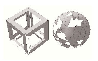
 The cube’s faces are smoothed with an angle that’s too
high, the sphere’s faces with an angle that’s too low (image1).
This is how the cube and the sphere should look
according to smoothing groups (image2).
Flipped Normals
Rendering the face of a geometric shape requires both the vertices that define it and
information about its orientation. This can be seen as information about which is the front
and which the back of the face, which is done by the surface normal as well. When
importing a model from a CAD package, you may find that direction information can get
lost or corrupted. The problem is that from the back, a polygon is invisible and appears
as a hole in the model. To fix this problem, try toggling ‘Backface Culling’ in the ‘Object
Properties’ dialog box, or assign a material and make it two-sided. If there are only a few
faces with the wrong orientation, you can add an ‘Edit Poly’ modifier and use Flip on the
affected faces. If the import is poor, you can use a two-sided material such as the
‘Arch+Design’ material to fix the faces without spending too much time on cleanup.
 The geometry is the same as in the preceding example, but some faces are flipped so they appear to be invisible.Orientation information can be lost or corrupted during import.
Polygon Count
It is good practice to think about how many polygons an object should consist of before
modeling it. This is true for all geometric objects, especially curved and round ones. Each
face needs to be rendered, but using many polygons on a round object can quickly add
up to inefficiencies, especially if objects are copied within the scene. On the other hand,
using too few polygons makes an object appear segmented.
 Picking a polygon count that is too low for your model gives unsatisfactory results for architectural rendering (image1-2).
In this example, the bowl’s appearance is improved because the shape allows for additional faces without destroying the bowl itself; you could simply add a ‘Turbosmooth modifier’(image 3-4).
Unwelded Vertices
In some cases, a model might look as if it is closed, but instead
each face is separated and the vertices of neighboring faces are
unwelded—that is, not connected. Unwelded vertices can introduce
many problems, including large file sizes due to thousands of
unnecessary vertices, damage to the object when moving faces or
altering the model, and even problems with proper smoothing and
normal interpolation, since the faces appear unconnected to 3ds
Max. If the ‘Smooth modifier’ doesn’t correct smoothing problems,
check for unwelded vertices. To weld vertices, simply add the
‘Weld Vertices’ modifier and choose an appropriate radius.
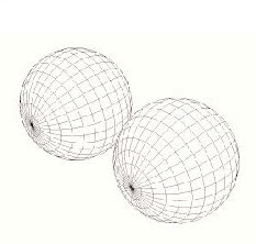 Both spheres look the same, but the right one has a row of unwelded vertices. This wastes memory (for example, instancing an object many times) and makes it difficult to modify geometry.
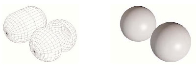 Problems appear when moving half the faces with an ‘Edit Poly’ modifier. Welding the vertices corrects the loose edges (image 1).
Under certain light conditions you can even see unwelded vertices by studying a render of the object(image 2).
Overlapping Surfaces
Watch out for faces that overlap precisely. The renderer cannot determine which one to
put in front, and a black pattern artifact will appear. Overlapping faces can be introduced
by careless modeling or by importing a file, such as a CAD file with versioned geometry
overlapping precisely on several layers.
Light Leaks
Since indirect lighting calculations have to be interpolated in some way because of their
complex nature, it is crucial to avoid light leaks when modeling. Light leaks are caused by
geometry, usually edges, that let indirect light pass through, even if this would not happen
in the real world. The problem is most obvious in scenes with high contrast, such as sunlight
on an enclosed space with an opening. If not modeled properly, faulty geometry can
let light pass into the space through open edges.
Even if your model looks good in the viewport, it might show light leaks during rendering.
Check your render setup for possible causes. For example, radiosity might let light crawl
underneath a wall if the floor is not disconnected. If the photon search radius is set too
high for thin walls, the sun will be interpolated to the inside. Final Gathering is usually the
most robust way to work around potential light leaks.
