


So far in a number of our projects, we find that conceptual and early schematic design usually involves still using 2D cad to either explore design options, or because the staff doesn't have the Revit experience yet (and may never :) ). We recently ran through an exercise on a project in that situation that I thought was useful.
This project had the elevations drawn in ACAD, by the designer (base on Revit elevations).
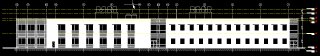 Under closer inspection, the elevation can be broken down into 4 seperate zones.

We can then figure out how we think we might model these 4 zones in revit, essentially planning and to a certain extent desiging the wall system(s).
Metal Panel

Here we planned on a dual system. The primary wall is supposed to be metal panel (grey) with stud backup. To acheive this, curtain wall will be used with a thin mullion recessed to create the joint lines. Behind the C.W. system will be a basic wall with; insultation, sheathing, studs, interior finish.
Nested in the metal panel C.W. as a panel will be another C.W. with glazed (L. Blue), spandrel (D. Blue), and custom louver (yellow) panels.Openings will have to be cut in the stud back up wall, and custom mullions will need to be used on the nested C.W. for where the glazed portions occur.
Custom mullions must be used on the nested curtain wall, otherwise it is not possible to offset the storefont mullions correctly from the metal panel "mullions". This is a known issue that Autodesk is working on. The openings in the stud back-up wall are going to be created with custom window families.
Store Front in Brick

Here we move into a more typical basic wall type. However even though the first reaction might be to make one single wall from ground to roof, we have found that it is typically easier to break walls up into seperate parts. In this case the horizontal lines represent where the wall is going to be broken up. Starting from the top there will be a "parapet" wall type, next will be a "mid level" wall type, and last will be the "lower level" wall type. There are several good reasons for doing this.
a) expeience has shown that in many cases walls that span multiple levels cause more problems then they solve due to wall join conditions (specically single level walls intersecting near to each other at different levels)
b) the lower level wall can include the base/water table as an integral sweep or split layer. Split layers are preferable, as the bottom can be un-locked, allowing the base level to be the first floor, but the base can easily be extended down for changes in grade, etc.
c) the parapet wall is really a different construction from your typical wall construction. If you really wanted to take this a step further, there would be another wall type for above the ceiling line. This wall type would might not include an interior finish, etc.
The storefront (yellow) is identical to the storefront that is nested in the metal panel, so the same pieces will be used here as well. In fact the embedded storefront can be grouped, making it very easy to quickly copy (and modify) the storefront down the length of the building. As a group, if you modify one (adjust mullion location, panel type, etc) they'll all change!
The next piece is the header (in green), this wil probably be a custom wall hosted family of some type, that gets inserted into the wall.
The last, and trickiest piece is the area in magneta. This is three columns of stacked bond brick, with each row recessed. We're not sure yet if this will be done with wall types, or a custom family of sometype. We'll have to see what seems to work best.
Curtain Wall
Not much to say here, except that some of the same pieces used in the storefront systems will be used here.

Brick Wall with punched windows
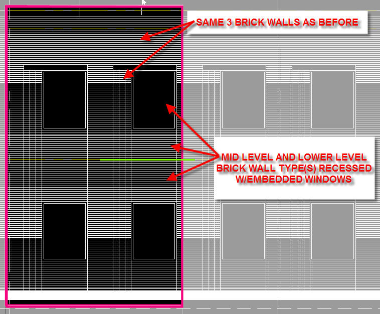
This wall will follow the same strategies as the other brick wall. Except the punched windows will either be an embedded C.W. system or actual window families. Depends on how the team wants to schedule the units. The only difference is that there will need to be additional pieces of brick wall recessed with the windows, the walls will be split at the floor level similar to the primary brick wall pieces.
I hope you find this helpful. This is a worthwhile exercise even if the whole team knows Revit, and the project is already started. It doesn't take very long either, in this case we came up with this in 30-45 mins over the phone, with screen sharing.
The exercise helps to establish what wall types need to be created, custom families required, and exposes problems that might come up. I have typically found that often times, if Revit is having a problem with constructing a condition, then it is probably a condition where you as the architect will need to pay attention to the detailing. Even in this case there are a couple of conditions where the team doesn't know exactly what they're going to do, but some ideas have already been developed.
1 comment:
Post a Comment