Revit Tutorials ,Revit libraries, Revit rendering,Bim revit, Headline Animator

Revit Tutorials ,Revit libraries, Revit rendering,Bim revit,

Check this out


Autodesk Revit Tutorial Headlines

Friday, June 12, 2009

Revit The Ultimate Tool for Green Future

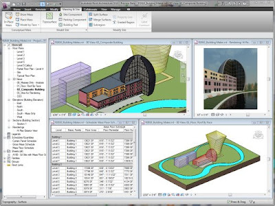
Building Information Modeling (BIM) has infiltrated the BSD community and is making its mark with many firms. One of the leading programs is Autodesk's Revit Building. This program incorporates both 3D modeling and 2D drafting in one. The purpose of this article is not to glorify Revit or denounce AutoCAD, but rather to give insight to the end user on whether or not to at least venture into BIM technology. Revit has many topics worth noting, however, I will just touch upon two..

The Parametric Change Engine

So what exactly is Revit? Revit is much more than a drafting and modeling program. It is based on Building Information Modeling (BIM) technology. Revit, which stands for 'revise instantly', uses BIM to create a working, living, breathing model. Using the idea of parametric change technology greatly increases productivity, workflow, and collaboration efforts. Take for example, AutoCAD. Within CAD if a window is deleted or altered, that change has to be manually updated in the file, schedules if any, xref's and any other views et cetera.

In Revit, users are able to utilize the parametric change technology and not have to worry about updating the model. When a window is deleted or manipulated within a view, it is updated throughout the entire project including schedules, isometric views, sections, elevations, and walkthroughs etc. The parametric change engine allows the user to update one item and not have to worry about changing that same information throughout. I like to say your project has the three C's in that your design and documentation stay coordinated, consistent, and complete

Worksharing and Projects

In this scenario, a firm has a residential project; one person would not work entirely on every discipline. Within Worksharing, one user will set the basic layouts and components needed for the project start. For example, an exterior shell, interior partitions, furniture layout, HVAC, conveyances, site components, and electrical components are some aspects that go into design. Once the basic layout is structured and laid out, that user will then place each of those components into worksets. Each workset corresponds to a particular design field i.e.: the exterior walls being placed into the "exterior shell" workset. Once that is done, the user will save the project file to a central file. This central file is located on a drive or folder that all users will have access to.


Once the central file is saved, users then access the file on their workstations, and save the central file locally under their username. Each local file can only be altered by that user. When the user opens his/her file, they can "check out" certain worksets. For example, if John is designated to work on the interior partitions, then he can check out the "partitions workset" and only he will be allowed to manipulate the set. Once all amendments are complete, the user will save his/her file to the central file and the updates will be saved to the central file. Each member of the design team will then reload their file thus making it current. The worksharing capabilities go further in depth but you can see how the members of the design team are in sync with one another, thus keeping consistent and coordinated files.

In addition to checking certain worksets out, you are able to "borrow" elements from a users work set. If John is working on the interior partitions and needs to move or delete a window on the exterior shell workset, he can click on an icon and ask permission from that user to borrow that certain element. On the other end, for that user to be notified about the borrowed element, John would have to either call or email the end user and notify him to check his "edit request" icon. This helps to control the project so that no two people are working on the same objects and worksets.

Benefits and Future of Revit

Revit has many features that allow users the flexibility and freedom to design in a manner that does not constrain them to just 2D drawings. BIM technology and the parametric change engine are the two components which make Revit an incredible force in the BSD community. Autodesk has launched the Revit Architecture Suite (RAS) which includes a copy of both Revit Architecture and AutoCAD. Even with new technological advances to BIM, there are a few things to keep in mind. Overcoming the resistance to change and getting users to understand the potential of Revit are two issues firms must deal with. The utilization and functionality of Revit requires an investment and a commitment to take on a new program. Proper training and project management must also be administered. These are some issues to think about when looking into Revit.

Thursday, June 11, 2009

But What if I Don't Want to Edit XML?

But What if I Don't Want to Edit XML?

There's a whole lot of variety in the MEP world; from the different system types that can meet the occupancy requirements of a building, to the different standards that can be used to create each of those system types, to the different materials and connection types that can be used to for a given standard for a given system type...you catch my drift.

The Wall of Blinking Lights, Switches, and Knobs

Istock_000001305694xsmall_2

For us as a product team, it means that we need to architect an application that is flexible enough to meet those needs, but is not a "wall of blinking lights, switches, and knobs".  While the "wall of blinking lights, switches, and knobs" certainly does accomplish the task, it's not the most usable or learnable solutions.

The guy who's been working at that wall for 10 years?  Well he's got that wall down, ask him to do something and he know which knob to turn to get the desired result.  If that guy gets hit by a bus, or decides he wants to work somewhere else, then the next guy just kind of stares at the wall in awe while there is a near meltdown because the Safety Inspector in Sector 7G is working from home due to an obesity disability claim (Simpsons referenece).

The contrary solution involves good UI design, user testing, and a lot more resources.  Therefore, as a product team we must pick and choose where we apply our finite resources to provide the more usable and learnable product, while still making sure it is still a capable one.  Just a little insight into our decision-making process.

The Old Way - In an XML File

With that in mind, we've made a nice step (admittedly biased opinion) forward with Revit MEP 2009 regarding a piece of functionality that was previously such a "wall of blinking lights, switches, and knobs".  As a way of delivering the aforementioned application flexibility, we previously kept record of the sizing information available for both Pipes and Wire for a given Revit project in XML files.

We willed these XML files with the information we felt was needed for a good chunk of our users' projects.  But, due to the aforementioned variety in the MEP industry, there was need to add more information to these XML files.  Simple enough, if you were comfortable editing XML files.  That is a big "IF", and certainly not the most learnable or usable solution.

Add to that fact that for projects with customized XML files, those XML files had to be accessible to every user working on that project, or else some users would not be able to use these custom sizes/materials.  This created an additional coordination hurdle for CAD/BIM Managers.

In short, we had a bit of a "wall of blinking lights, switches, and knobs" on our hands.

The New Way - In the Project

So in Revit MEP 2009 we have moved this previously XML-based information into the Revit Project file itself, creating a much more usable/learnable solution.  At the same time, we have made users aware that such capability existed in the first place...all good things.

Size List Migration

Note: Be sure to Right-Click->Zoom->Full Screen inside of the embedded video player to see it in all its 1024x768 beauty.  You you can download the full video by clicking on the linked title.

As you can see, this is a nice enhancement to the previously available functionality, and with the Transfer Project Standards functionality, it's a straightforward process to move your customized settings from one project to another.

Now, for those of you who managed to navigate the previous "wall of blinking lights, knobs, and switches", we did not forget about you.  Watch the following video for the process to migrate this previously customized data from Revit MEP 2008 into Revit MEP 2009.

Migrating Custom Settings from 2008 to 2009

Note: Be sure to Right-Click->Zoom->Full Screen inside of the embedded video player to see it in all its 1024x768 beauty.  You you can download the full video by clicking on the linked title.

I hope that helps to cover this new functionality.  As always posts comments/questions you have and I'll try to answer.

Visit contributor's website - http://inside-the-system.typepad.com

STL Exporter for Revit Platform 2009

STL Exporter for Revit Platform 2009

Create 3D Prints of your Revit 2009 models. As architects and engineers start their digital designs earlier and keep them digital for longer, they want a way to still physically interact with their designs. With the economical availability of 3D printers this has become possible. 3D printed models increasingly serve as a critical part of the design process to study design options and improve communication between project members and owners. The STL Exporter for the Revit 2009 family of products is a proof of concept project that we are working on. It is designed to take a 3D Revit building information model and create an STL file that can be used for 3D Printing. We invite you to take it for a spin and see what you think. We look forward to hearing your feedback.

To Get Started

  1. Download the ZIP package that cantinas the installer, installation and user instructions, and a feedback form.
  2. Unzip the downloaded ZIP file.
  3. Follow the Read Me file to install the STL Exporter.
  4. The next time you open Revit 2009 you will see a new option called Export STL under the Tools::External Tools menu.

To Use It

  1. Load a model and select a 3D view that you want to use as the bases for your print.
  2. Using the instructions in the Read Me file set up your 3D view in the one of the Revit 2009 family of products.
  3. Export the model using the command under the Tools::External Tools menu.
  4. Make any required changes to the STL file using an STL viewer.
  5. Print the STL file using a 3D Printer.
  6. Enjoy the fruits of your labor!

Download available at: http://labs.autodesk.com/utilities/revit_stl/term_and_condition/

contributor-http://bimandbeam.typepad.com/

Duct Size Parameter - Inches - Revit MEP

Duct Size Parameter - Inches - Revit MEP

If you used AutoCAD before using Revit you likely went through a bit of withdrawal from using inches as a base drawing unit. With Revit you had to get used to typing 0 space 6 for 0'-6" or 0 dash 6. Well in Revit MEP there is one instance at least where you get to enter relevant values when working through your design.

First if you are interested I posted a little video overview of this subject. Otherwise read on...

I am referring to the duct size parameters as the title suggests. In the Family Editor > Family Types dialog we can choose to Add Parameters to our family. Aside from providing a clever name we also can choose the Discipline > HVAC which in turn offers quite a few choices for "Type of Parameter".


When you choose Type of Parameter: Duct Size, Revit will require you to enter values in inches, which is easier since most duct sizes are referred to by their size in inches.

There's a catch though if you like to add parameters by using the Associate Family Parameter "sneaky button" in the properties of elements in the Family Editor.


This route precludes the use of the HVAC Discipline, Type of Parameter choices as it defaults to common and its subset of Types of Parameters. Not FAIR I say! I'm sure it is just an oversight!

To use it you need to start with Family Types > then Add Parameter. Then you can Associate the family parameter with the Element's parameter.
 
 Contributor - http://revitoped.blogspot.com visit for more...

How to tag doors by Type or tag windows

How to tag doors by Type or tag windows

Currently, Revit tags doors by Mark and tags windows by Type. So how do you tag doors by Type instead of by Mark, or tag windows by Mark instead of Type?

The Revit annotation family used in the project dictates the information in the door and window tags, as well as the appearance of the tag. By default, doors tags are oval with the door number centered in the tag and window tags are hexagons with the window Type centered in the tag.

In order to tag doors so that the Type appears in the tag instead of the Mark, or to tag windows so that the Mark appears in the tag rather than the Type, you need to load a different annotation family component. Revit Architecture comes with an alternate window tag that tags the window by Mark. For doors, you'll need to create a new tag that uses the Type instead of the Mark. This is easily accomplished.

It's easier to take an existing family component and modify it rather than creating one from scratch. Open the existing door or window tag family (.rfa) by selecting File > Open and then navigate to the library folder in which the tag is stored (by default, door and window tags are located in Imperial Library > Annotations > Architectural).

The tag opens in the Revit family editor.

Select File > Save As and give your new tag an appropriate name (such as Door Tag by Type.rfa) and click Save. This will preserve the original tag.

Select to highlight the label text.

On the Options bar, click the Select Parameter button.

In the Select Parameter dialog box, select the parameter you want to assign to the label. For example, to create a door tag that labels the door using the Type rather than the Mark, select Type Mark. In the Value field at the bottom, enter a value to represent the label for the family.

Then click OK.

Select File > Save. Then close the family editor.

To use your new tag, load it into your project (File > Load From Library > Load Family).

http://newsletters.hagerman.com/newsletters/ebul66-AEC.htm visit contributor blog

Revit MEP Tricks and Tips Part #1

Revit MEP Tricks and Tips

Sometimes it's the little things which make all the difference. I thought I would share some nifty tricks that can help make Revit MEP go down a little easier.

  1. Use the space bar to inherit duct and pipe sizes from objects you have connected to instead of uses the last used size. Hit the space bar again to cycle back to the last used size.
  2. Tap the space bar to rotate Light fixtures 90 degrees before you insert them. Hold your cursor over an angle wall and tap the space bar to have you light fixture or diffuser align to that wall or go perpendicular to it..
  3. Tabbing while hovering over a duct or pipe will highlight portions or the entire run (system).
  4. Use your keyboard's arrow keys to nudge selected objects left, right, up and down small distances.
  5. Type CM to add every single available object type to the type selector. I use this when I can not remember the family type. CM loads them all.

Rotational Parameters and Face-Based Nested Families

Rotational Parameters and Face-Based Nested Families

We often come across requests or recommendations for adding rotational controls to family geometry.  This is most commonly present for door swings, hinge type families, or geometry which needs to rotate around a given point in a family.  I wanted to pass along a recommendation which typically works well.

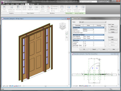
The first step is to separate the family geometry [which will be rotated] into a separate face-based family.  Face-Based families offer additional flexibility when placing the nested family into the host family.  By utilizing a reference line for the rotational basis, the face-based family can be hosted onto the reference line by the "Place on Work Plane" option.  By using the "TAB" key the two planes of the reference line can be specified, as well as the "SPACE" key to designate the nested family rotation during placement.

Family 

With the reference line in place and an angular dimension parameter attached, the nested face-based family will rotate with the reference line it is hosted on.  I have outlined an example process in the video below:

Video Example

Please keep in mind this process can be applied to other scenarios for family creation.  I typically recommend a reference line over a reference plane because a reference line can be aligned and constrained using the end point.  This is often useful for a family rotating along an end point.  In addition you can check the "Shared" option in the nested family under "Category and Parameters" to ensure visibility and scheduling occur as needed.

Wednesday, April 29, 2009

Showing hidden lines of in-place Families.

Showing hidden lines of in-place Families.

Quite often In-place Families families don't show their hidden lines and the show and remove hidden line tools are disabled when the graphics style is set to hidden line.

Strange but true.

If you switch the view discipline from Structural to Architectural then these tools are enabled.


Apply the hidden lines by first clicking the object you want to see through, then the object you want to see under.

Remember to switch your view back to Structural afterwards.


-----Autodesk--------Revit----Architeture----Tutorials----------
For more Autodesk Revit Tutorials
Go to http://www.revittut.blogspot.com to learn more

Parameter Binding Performance

Parameter Binding Performance

Here is a short but important question that has come up repeatedly concerning the performance of parameter bindings.

Question: There is a big problem in the early versions of Revit 2009 with the performance of the Document ParameterBindings property, for example in the last line of the following code:

Application app = commandData.Application; Document doc = app.ActiveDocument; BindingMap bindingMap = doc.ParameterBindings; 

The last statement takes a huge amount of time to execute, in the order of minutes. Are there any known solutions for this?

Answer: Good news: this performance delay was analysed and reported by Saikat Bhattacharya and fixed in the Revit 2009 Web Update 3. The issue is mentioned in the associated PDF file containing the list of enhancements:

API Enhancements

  • Parameter binding performance has been improved.
  • The JoinType method has been implemented for the LocationCurve of structural members.
  • Mullion LocationCurves are now accessible through the API.
  • External programs may now suppress VSTA startup warning messages.
  • The built-in parameter MATERIAL_PARAM_TRANSPARENCY now returns the correct set value.

So all you need to do is install the updated version of Revit 2009 and the problem disappears. Many thanks to Saikat for pointing this out.


-----Autodesk--------Revit----Architeture----Tutorials----------
For more Autodesk Revit Tutorials
Go to http://www.revittut.blogspot.com to learn more


Back to Basics: Mark and Type Mark

Back to Basics: Mark and Type Mark

Language...with Revit's parameter naming the follow is true:

Door Number = "Mark" (not the person but the signature, ID or identifying "mark")
Window "type" = "Type Mark"

Out of the box, Revit's tags are assigned to these as described above. A door number is unique for each door so its tag is using a label assigned to the "Mark" parameter. Windows, for the most part, are defined according to a "type", a common letter or number designation for each window of a given "type" or configuration, therefore a window's tag is assigned to the "Type Mark" parameter.

"Mark" is located in the Element properties dialog while "Type Mark" is located in the Type Properties dialog. Most of Revit elements have both. Some Mark values are automatically supplied based on the "last" value entered and many are not. Type Mark values are not supplied with the assumption that each project will have its own needs and will be defined accordingly.

If you don't approve of the out of the box setting, you can create your own tag so that you can properly identify an element according to your needs.


-----Autodesk--------Revit----Architeture----Tutorials----------
For more Autodesk Revit Tutorials
Go to http://www.revittut.blogspot.com to learn more


Revit 2010 Enhancements


Revit 2010 Enhancements

There are a few enhancements I want to cover in Revit 2010 which may get lost in the shuffle behind the user interface and conceptual mass tools.

Gradient Backgrounds

In 3D views, there is a new option under "View Properties", "Graphic Display Options", "Background", for "Gradient Background".  Checking this box will allow you to specify a "Sky Color", "Horizon Color" and "Ground Color".

Gradient-Background-1 

This is useful to add some additional depth to shaded 3D views:

Gradient-Background-2 

Halftone / Underlay Control

You now have specific control for the level of halftone for objects or linked files.  Under the "Manage" tab, "Settings" pull-down, choose "Halftone/Underlay".

Halftone-Underlay 

The default is 50% brightness which can now be adjusted as needed.  This value will be utilized when objects or linked files utilize the "Halftone" checkbox throughout the project.

In the same menu you will find the "Underlay" variables for "Weight" and "Pattern".  "Weight" specifies the line weight for underlays where "Pattern" specifics the line pattern for underlays.  These settings will become active when an underlay is utilized in a view.

---------------------------------------------------------------------------
For more Autodesk Revit Tutorials
Go to http://www.revittut.blogspot.com to learn more


The Ribbon Process in Four Minutes

The Ribbon Process in Four Minutes

Designing and implementing this overhaul of the user interface required a considerable amount of research, data analysis, interaction design, and visual design. I put together a four minute video that was presented to the senior Autodesk executive staff last month. It briefly describes some of the design methods that we used while integrating the ribbon into the three Revit products. This video highlights a few themes that will persist through our blogging on the topic:

  • Using data to make design decisions
  • Developing prototypes and iteratively testing them with customers
  • Leveraging design patterns to create flexible and extensible designs


---------------------------------------------------------------------------
For more Autodesk Revit Tutorials
Go to http://www.revittut.blogspot.com/ to learn more

Wednesday, April 15, 2009

Revit Architecture 2009 UPDATE

Revit Architecture 2009—English

IMPORTANT

This download is the most recent build for Revit® Architecture 2009 software as a standalone product and as part of AutoCAD® Revit® Architecture® Suite 2009.

It is available to users who have validly purchased a license to Revit Architecture 2009 or AutoCAD Revit Architecture Suite 2009, and is subject to the terms and conditions of the end-user license agreement that appears during installation.

For a list of improvements, please download the Revit Architecture 2009 Web Update Enhancement List:

Web Update Enhancement List (pdf)
Note: Build Number can be found in the Web Update Enhancement List


Web Update #3 Service Pack – November 2008

Important Note:
Web Update #3 is not a full install; rather it is using Service Pack technology similar to AutoCAD® based products. Prior to installing the Web Update #3 Service pack, please verify that you have already installed a previous build of Revit Architecture 2009. The full install of Revit Architecture 2009 (32-bit) Web Update #1 is available below. The full install of Revit Architecture 2009 (64-bit) can be downloaded from the Subscription Center.

Before You Download

Please read before downloading and installing:
Service Pack Readme (pdf).

Get Started

Read all instructions above then click the appropriate link to download.

Revit Architecture 2009 Web Update #3 Service Pack (32-bit) (exe - 128 MB)

Revit Architecture 2009 Web Update #3 Service Pack (64-bit) (exe - 54 Mb)

Notes:

  • The service pack contains changes from all previous Web Updates.
  • The service pack can be applied to both the standalone and Suite versions of Revit Architecture 2009.

  • Web Update #1 Full Install – June 2008

    Before You Download

    Before downloading and installing:

    • Read this first (pdf).
    • Locate the name of the software you wish to download.

    Get Started

    Read all instructions above then click one of the following links to download.

    Notes

    • It is highly recommended that you reinstall the content when installing the Web Update due to changes in the rendering library and other pieces of content.
    • Downloads are applicable only to licenses under subscription, worldwide.
    • Files saved in new releases of this product are not compatible with previous releases. However, files saved in the same release are compatible across different build numbers.
    • Microsoft® Internet Explorer® 6 is required.
    • For problems downloading or installing Revit Architecture 2009 and for general information or questions, contact Autodesk Revit Support (Autodesk® Subscription login required).

    Monday, April 06, 2009

    Autodesk® Revit® Architecture 2010 Rocks!!!!

    Top 10 Reasons to Choose Autodesk® Revit® Architecture 2010 software

    Conceptual Design Environment


    New and innovative Autodesk Revit Architecture conceptual design features provide
    easy-to-use tools for free-form modeling and parametric design, and the ability to
    perform early design analyses. Sketch freely, create 3D forms quickly, and manipulate
    forms interactively. Prepare your models for fabrication and construction with built-in
    tools for conception and clarification of complex forms. Autodesk Revit Architecture
    automatically builds a parametric framework around your most complex forms as you
    continue to design, offering you greater levels of creative control, accuracy, and
    flexibility. Take your design from concept model all the way through construction
    documents, all within one intuitive environment.

    Building Maker

    The Building Maker feature in Autodesk Revit Architecture helps you transform your
    conceptual forms into fully functional designs. Select and add faces to design walls,
    roofs, floors, and curtain systems. Extract important building information, including
    gross area per floor. Bring conceptual massing concepts from applications such as
    AutoCAD® software and Autodesk® Maya® software, as well as AutoDesSys form•Z®,
    McNeel Rhinoceros®, Google™ SketchUp®, or other ACIS®- or NURBS-based
    applications into Autodesk Revit Architecture as mass objects and begin schematic
    design.

    Bidirectional Associativity


    A change anywhere is a change everywhere. In Autodesk Revit Architecture, model
    information is stored in a single, coordinated database. Revisions and alterations to
    information are automatically updated throughout the model, minimizing conflicting
    versions and significantly reducing unpleasant surprises.

    Parametric Components

    Parametric components, also known as families, are the basis for all building
    components designed in Autodesk Revit Architecture. These components offer an
    open, graphical system for design thinking and form making, while providing the
    opportunity to adjust and express design intent at detailed levels. Use parametric
    components for the most elaborate assemblies, such as cabinetry and equipment, as
    well as for the most elementary building parts, such as walls and columns. Best of all,
    no programming language or coding is necessary or required.

    Schedules

    Schedules provide another view of the comprehensive Autodesk Revit Architecture
    model. Changes to a schedule view are automatically reflected in all other views.
    Functionality includes associative split-schedule sections and selectable design
    elements via schedule views, formulas, and filtering.

    Detailing

    The extensive detail library and detailing tools provided within Autodesk Revit
    Architecture enable extensive presorting, easing alignment with the CSI format. Detail
    libraries can be created, shared, and tailored to accommodate your office standards.

    Material Takeoff

    Calculate detailed material quantities with the Material Takeoff feature. Ideal for use on
    sustainable design projects and for precise verification of material quantities in cost
    estimates, this feature significantly smoothes the material quantity tracking process.
    As projects evolve, the Autodesk Revit Architecture parametric change engine helps
    ensure material takeoffs are always up to date.

    Intuitive User Interface

    The new release of Autodesk Revit Architecture features a streamlined user interface.
    Find your favorite tools and commands faster, locate lesser-used tools more efficiently,
    and discover relevant new features more easily. The result is less time searching
    through menus and toolbars, and more time getting your work done.


    Sustainable Design

    Autodesk Revit Architecture supports sustainable design processes from the earliest
    stages. Export building information to green building extensible markup language
    (gbXML). Perform energy analysis using Autodesk® Green Building Studio® webbased
    services, and study building performance employing Autodesk® Ecotect™
    software. Use Autodesk® 3ds Max® Design software to accurately evaluate indoor
    environmental quality in support of LEED® 8.1 certification.

    Design Visualization

    Create and capture fully photorealistic design ideas and contextual environments to
    experience your project, even before it is built. Integrated mental ray® rendering helps
    deliver high-quality output, faster render times, and a superior design presentation.

    Wednesday, January 07, 2009

    Known Issues Autodesk Revit MEP 2009 page2

    AUTODESK REVIT® MEP 2009 - Known Issues Autodesk Revit MEP 2009

    Default Pipe Size Information
    · The first time you open a project that was created in a previous release, Autodesk Revit MEP attempts to import pipe size information from the PipeSize.xml file used with the prior release. The imported information overwrites the integrated default pipe size information. If you want to preserve custom size information from a prior release, you must restore the PipeSize.xml file used with the project to its original path. There is no warning message if the PipeSize.xml cannot be found. If you save the project in this release of Autodesk Revit MEP, without having imported the size information used with the prior release, the project will use the default size settings. For more information please refer to Autodesk Revit MEP Help.

    New Functionality Workshop
    Will not launch from the installer when installing on a Windows Vista 64 bit system.·
    Will not launch from the installer when installing from a network drive.·

    Control-Point Location on Homerun Arrows
    · The location of the control point that is used to grip and drag the arrow location of a homerun wire has moved from the tip of the arrow to the base of the arrow. This point location is also used to determine graphics for “automatic cleanup” that occurs when the homerun for one circuit is connected to, for example, a receptacle on a separate circuit. The end result is that the base of the arrow will be automatically located at the graphical boundary of the receptacle symbol, with the tip of the arrow extending into the receptacle (or whatever other device/equipment the homerun points to). To fix this problem, you can grip-edit and drag the control point on the arrow to the desired location.

    Export to ODBC
    · When exporting to ODBC, family instances within the project that have more than one connector will only export information associated with one of the connectors. The other connectors will be ignored.

    Heating and Cooling Loads Report
    · Results that are displayed in Heating and Cooling Loads reports may appear to be non-precise. For example, a cubic room that is 20ft x 20ft x20ft may display a volume of 8,000.01CF instead of 8000.00CF. This is due to rounding differences that are introduced during the conversion to metric units so that the calculations can be performed, and then back to imperial units for display in the report.

    Space areas· that are calculated and displayed in the Heating and Cooling Loads reports could be based on either the internal faces or external faces of the wall. There is no way for the user to control this. By default, the first attempt is to use the inner faces of the walls. However, due to current technical limitations, there are cases where it may not be possible to use the inner surfaces of the walls, in which case the area calculations will be based on the location of the outer wall surfaces.

    Design Phases in the MEP Workflow
    · Using design phases in the Autodesk Revit MEP workflow may result in unexpected behavior. For example, if 3 air terminals with a flow of 500 CFM each are created in one duct run, then the flow reported on an upstream pipe would be 1500CFM (as expected). However, if one of those terminals is demolished in a different phase, then that same upstream duct will still report 1500CFM – regardless of which phase you are currently viewing. This is because it is not possible for a single duct run to be able to store multiple flow values simultaneously. Therefore, the systems values will always be representative of the all equipment/devices attached to the system. This similar type problem applies to all mechanical and electrical systems. Any system that is created has no way to keep track of information for multiple phases. This problem with phasing may also be manifested in ways other than what is specifically described above.
    When running Heating and· Cooling Loads calculations, only the spaces that are on the current energy analysis phase will be included in the calculations. All spaces must be on the same phase in order to be included in the calculations.

    Spell Check Dictionary Not Compatible With Office 2007
    · The spell checking functionality in the 2009 Autodesk Revit release is not compatible with the new Microsoft Office 2007 dictionaries (English, German, Spanish) due to Microsoft reformatting the dictionaries to a new proprietary format. The French, Dutch, and Italian dictionaries were not reformatted in Office 2007 and are still compatible with 2009 Autodesk Revit. Customers can use the provided Autodesk dictionaries or install an earlier version of Microsoft Office to use the older Microsoft dictionaries.

    Dimension Text Overrides
    · For a multi-segment dimension string in which one of the dimensions has had a dimension text override, adding a new segment to the string will cause the override to disappear.
    Dimension Type Text Sizes

    Dimension Types lose their previous Text Size changes when a Duplicate Type is created.·
    Fill Patterns

    Fill Patterns can now be applied to most surfaces (including warped planes), however:·
    o Only patterns on planar surfaces can currently be moved or rotated.
    o Some complex surfaces may exhibit undesirable anomalies (such as areas of missing pattern).

    Detail components do not currently support aligning fill patterns to the element·
    Dimension Text Overrides

    · For a multi-segment dimension string in which one of the dimensions had a dimension text override, adding a new segment to the string causes the override to disappear.
    Dimension Type Text Sizes

    Dimension Types lose their previous Text Size changes when a Duplicate Type is created.·
    Mass Floors in Groups

    Currently, when binding a link containing Mass Floors, they will disappear because they cannot be placed into groups.·
    Far Clip Parameter and Linked Files

    · While Linked files can now be displayed By Linked View in Sections, Elevation and 3D views, the Far Clipping Parameter in Section and Elevation views will always display per the Host view’s settings and NOT by the Linked View’s settings – even when the Link is set to display By Linked View.

    Large DWG Imports
    · DWG imports with entities further than two miles apart (after scaling) may cause accuracy issues. Very large DWG imports should be subdivided into smaller files.

    DWG imports with coordinates (before scaling) longer than ten digits may be truncated to zero and become corrupted.·

    Upgrading very large Autodesk Revit 2008 files
    · Upgrade of some very large Autodesk Revit files (~200 MB and greater) may cause Autodesk Revit to crash by exceeding the maximum memory usage allowed by the operating system. Please contact Autodesk Product Support immediately if encountering this problem.
    Rendering

    Autodesk Revit 2009 contains· a new rendering engine that makes major changes in the previous workflow. See the Autodesk Revit MEP Feature Summary and Help documentation for information and instructions.

    Currently, Decal bump image maps fail to import at the correct scale for cut-outs.·

    The Plant Height parameter does not scale the nested component correctly (RPC Content).·

    When rendering an uncropped 3D view, geometry may appear shifted. Workaround: turn on crop region for the view.·

    For lights, the “Emit from Line Length” parameter may not work properly unless the user has Soft Shadows enabled.·

    Non-English builds of Autodesk Revit currently display RPC ID’s instead of names for downloaded RPC Content.·

    ViewCube’s Front orientation in a published DWF
    · If the ViewCube’s Front orientation is changed from its default setting in Autodesk Revit, the change will not currently be reflected on the ViewCube in a published DWF.

    Slab Shape Edit
    · After clicking Pick Supports for a sloped slab, changing the Curved Edge Condition to “Project to Side” causes the shape edit to fail for some curved edges. A temporary workaround is to delete the offending curve.

    Room Bounding Instance Parameters
    Currently, not all room bounding elements (e.g. in-place ceilings and in-place floors) have an on/off Room Bounding parameter.·

    Foundation Extensions
    Openings do not participate in the Foundation Extensions feature, only Inserts.·

    Concrete End Joins
    New behavior is limited to Concrete Beams with the following properties:·
    o Rectangular Sections with Cross Sectional Rotation that equal 0, 90, 180, and 270 degrees.
    o Trapezoidal, T-shaped, and L-Shaped Sections with Cross Sectional Rotation that equal 0 degrees.

    Sections that do not qualify within these properties will exhibit old behavior.·

    Shape Handles are not available for elements participating with new behavior.·

    Type parameter changes will not automatically update concrete join geometry.·

    Automatic Join Geometry
    Hierarchal joining rules between element categories cannot be changed, e.g. Slabs always cut Columns when using Join Geometry.·

    Automatic Join Geometry does not occur between Wall and Slab categories.·

    It is not possible to disable automatic Join Geometry, but joins can be manually un-joined.·

    Joined geometry may impact performance.·
    Hidden Lines

    On-screen display of hidden lines may not match vector output (e.g. Print, Export) in some cases.·

    Some edges of Wall ends will not show as hidden.·

    All Edges of slab edge will show as hidden in a Plan view if obstructed by the Slab.

    Beam Extension and Mitering at end Join
    Mitering non-Concrete Beams is limited to 2 Beams of the same type within the same plane.

    Lines within the Beam family (e.g. hidden lines) will not Trim/Extend to the miter plane.

    Beam shape handles do not participate in extensions.

    Edit Beam Join editor is not available when a concrete beam is participating in the end join.

    · Beams that have been mitered at any time during their life will be cut by the Cut Plane in Plan Views using Medium/Fine Detail Level.

    Worksharing Monitor
    · The Worksharing Monitor tool may behave incorrectly if the Local (or Central) File names contain dots other than the dot before the .rvt extension.
    DWF Markups

    Markups made in Autodesk Design Review with the Freehand Markup tool do not import into Autodesk Revit with properties.

    REVIT® MEP 2009 - Known Issues Revit MEP 2009 page2

    Default Pipe Size Information
     The first time you open a project that was created in a previous release, Revit MEP attempts to import pipe size information from the PipeSize.xml file used with the prior release. The imported information overwrites the integrated default pipe size information. If you want to preserve custom size information from a prior release, you must restore the PipeSize.xml file used with the project to its original path. There is no warning message if the PipeSize.xml cannot be found. If you save the project in this release of Revit MEP, without having imported the size information used with the prior release, the project will use the default size settings. For more information please refer to Revit MEP Help.

    New Functionality Workshop
     Will not launch from the installer when installing on a Windows Vista 64 bit system.
     Will not launch from the installer when installing from a network drive.
    Control-Point Location on Homerun Arrows
     The location of the control point that is used to grip and drag the arrow location of a homerun wire has moved from the tip of the arrow to the base of the arrow. This point location is also used to determine graphics for “automatic cleanup” that occurs when the homerun for one circuit is connected to, for example, a receptacle on a separate circuit. The end result is that the base of the arrow will be automatically located at the graphical boundary of the receptacle symbol, with the tip of the arrow extending into the receptacle (or whatever other device/equipment the homerun points to). To fix this problem, you can grip-edit and drag the control point on the arrow to the desired location.
    Export to ODBC
     When exporting to ODBC, family instances within the project that have more than one connector will only export information associated with one of the connectors. The other connectors will be ignored.
    Heating and Cooling Loads Report
     Results that are displayed in Heating and Cooling Loads reports may appear to be non-precise. For example, a cubic room that is 20ft x 20ft x20ft may display a volume of 8,000.01CF instead of 8000.00CF. This is due to rounding differences that are introduced during the conversion to metric units so that the calculations can be performed, and then back to imperial units for display in the report.
     Space areas that are calculated and displayed in the Heating and Cooling Loads reports could be based on either the internal faces or external faces of the wall. There is no way for the user to control this. By default, the first attempt is to use the inner faces of the walls. However, due to current technical limitations, there are cases where it may not be possible to use the inner surfaces of the walls, in which case the area calculations will be based on the location of the outer wall surfaces.

    Design Phases in the MEP Workflow
     Using design phases in the Revit MEP workflow may result in unexpected behavior. For example, if 3 air terminals with a flow of 500 CFM each are created in one duct run, then the flow reported on an upstream pipe would be 1500CFM (as expected). However, if one of those terminals is demolished in a different phase, then that same upstream duct will still report 1500CFM – regardless of which phase you are currently viewing. This is because it is not possible for a single duct run to be able to store multiple flow values simultaneously. Therefore, the systems values will always be representative of the all equipment/devices attached to the system. This similar type problem applies to all mechanical and electrical systems. Any system that is created has no way to keep track of information for multiple phases. This problem with phasing may also be manifested in ways other than what is specifically described above.
     When running Heating and Cooling Loads calculations, only the spaces that are on the current energy analysis phase will be included in the calculations. All spaces must be on the same phase in order to be included in the calculations.

    Spell Check Dictionary Not Compatible With Office 2007
     The spell checking functionality in the 2009 Revit release is not compatible with the new Microsoft Office 2007 dictionaries (English, German, Spanish) due to Microsoft reformatting the dictionaries to a new proprietary format. The French, Dutch, and Italian dictionaries were not reformatted in Office 2007 and are still compatible with 2009 Revit. Customers can use the provided Autodesk dictionaries or install an earlier version of Microsoft Office to use the older Microsoft dictionaries.

    Dimension Text Overrides
     For a multi-segment dimension string in which one of the dimensions has had a dimension text override, adding a new segment to the string will cause the override to disappear.
    Dimension Type Text Sizes
     Dimension Types lose their previous Text Size changes when a Duplicate Type is created.
    Fill Patterns
     Fill Patterns can now be applied to most surfaces (including warped planes), however:
    o Only patterns on planar surfaces can currently be moved or rotated.
    o Some complex surfaces may exhibit undesirable anomalies (such as areas of missing pattern).
     Detail components do not currently support aligning fill patterns to the element
    Dimension Text Overrides
     For a multi-segment dimension string in which one of the dimensions had a dimension text override, adding a new segment to the string causes the override to disappear.
    Dimension Type Text Sizes
     Dimension Types lose their previous Text Size changes when a Duplicate Type is created.
    Mass Floors in Groups
     Currently, when binding a link containing Mass Floors, they will disappear because they cannot be placed into groups.
    Far Clip Parameter and Linked Files
     While Linked files can now be displayed By Linked View in Sections, Elevation and 3D views, the Far Clipping Parameter in Section and Elevation views will always display per the Host view’s settings and NOT by the Linked View’s settings – even when the Link is set to display By Linked View.
    Large DWG Imports
     DWG imports with entities further than two miles apart (after scaling) may cause accuracy issues. Very large DWG imports should be subdivided into smaller files.
     DWG imports with coordinates (before scaling) longer than ten digits may be truncated to zero and become corrupted.
    Upgrading very large Revit 2008 files
     Upgrade of some very large Revit files (~200 MB and greater) may cause Revit to crash by exceeding the maximum memory usage allowed by the operating system. Please contact Autodesk Product Support immediately if encountering this problem.
    Rendering
     Revit 2009 contains a new rendering engine that makes major changes in the previous workflow. See the Revit MEP Feature Summary and Help documentation for information and instructions.
     Currently, Decal bump image maps fail to import at the correct scale for cut-outs.
     The Plant Height parameter does not scale the nested component correctly (RPC Content).
     When rendering an uncropped 3D view, geometry may appear shifted. Workaround: turn on crop region for the view.
     For lights, the “Emit from Line Length” parameter may not work properly unless the user has Soft Shadows enabled.
     Non-English builds of Revit currently display RPC ID’s instead of names for downloaded RPC Content.
    ViewCube’s Front orientation in a published DWF
     If the ViewCube’s Front orientation is changed from its default setting in Revit, the change will not currently be reflected on the ViewCube in a published DWF.
    Slab Shape Edit
     After clicking Pick Supports for a sloped slab, changing the Curved Edge Condition to “Project to Side” causes the shape edit to fail for some curved edges. A temporary workaround is to delete the offending curve.
    Room Bounding Instance Parameters
     Currently, not all room bounding elements (e.g. in-place ceilings and in-place floors) have an on/off Room Bounding parameter.
    Foundation Extensions
     Openings do not participate in the Foundation Extensions feature, only Inserts.
    Concrete End Joins
     New behavior is limited to Concrete Beams with the following properties:
    o Rectangular Sections with Cross Sectional Rotation that equal 0, 90, 180, and 270 degrees.
    o Trapezoidal, T-shaped, and L-Shaped Sections with Cross Sectional Rotation that equal 0 degrees.
     Sections that do not qualify within these properties will exhibit old behavior.
     Shape Handles are not available for elements participating with new behavior.
     Type parameter changes will not automatically update concrete join geometry.
    Automatic Join Geometry
     Hierarchal joining rules between element categories cannot be changed, e.g. Slabs always cut Columns when using Join Geometry.
     Automatic Join Geometry does not occur between Wall and Slab categories.
     It is not possible to disable automatic Join Geometry, but joins can be manually un-joined.
     Joined geometry may impact performance.
    Hidden Lines
     On-screen display of hidden lines may not match vector output (e.g. Print, Export) in some cases.
     Some edges of Wall ends will not show as hidden.
     All Edges of slab edge will show as hidden in a Plan view if obstructed by the Slab.
    Beam Extension and Mitering at end Join
     Mitering non-Concrete Beams is limited to 2 Beams of the same type within the same plane.
     Lines within the Beam family (e.g. hidden lines) will not Trim/Extend to the miter plane.
     Beam shape handles do not participate in extensions.
     Edit Beam Join editor is not available when a concrete beam is participating in the end join.
     Beams that have been mitered at any time during their life will be cut by the Cut Plane in Plan Views using Medium/Fine Detail Level.
    Worksharing Monitor
     The Worksharing Monitor tool may behave incorrectly if the Local (or Central) File names contain dots other than the dot before the .rvt extension.
    DWF Markups
     Markups made in Design Review with the Freehand Markup tool do not import into Revit with properties.

    Saturday, January 03, 2009

    Revit Families - Content Creation page 2

    figure 13
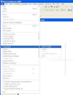
     Use the Import/Link Cad Formats from the File pull down to import
    the SAT file (figure 14).

    figure 14
     The Object comes in as an imported symbol and is not editable as
    Revit Geometry (figure 15).


    figure 15
     For each different size you would import an SAT for that size within
    the same Revit family file; then set as types with visibility
    settings; or create another family file for each size.
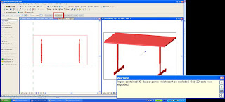
     As imported geometry these 3D objects cannot be exploded to turn
    into Revit Geometry (figure 16).

    figure 16
     As an imported symbol this SAT geometry is all assigned to "layer" 0
     This limits the ability to assign different materials to the
    discrete parts in Object Styles (figure 17).


    figure 17
     When the material is set to the Object Styles layer for imported
    objects, all the parts display the same material (figure 18).

    figure 18
    Just as when creating content from scratch in the Family Editor,
    imported SAT geometry family files can have identity, design and
    engineering data assigned as parameters in the family (figure 18).

    figure 18
     Although the imported SAT geometry can be dimensioned and aligned
    to, it cannot respond to dimension parameter constraints for size
    modification like native Revit geometry.
    Sat imported geometry
    Native Revit geometry
     Finally like creating geometry from scratch, save and name the file (.rfa)
     Load into Projects (.rvt) from the Family Editor (figure 19) or from
    the Project itself (Load from Library)
     Then place the family as a component when needed (figure 20)


    figure 19 figure 20
    Option3: Create from Imported dwg file in Revit Family Editor
     Model in Inventor
    Extraneous parts are suppressed and complex models can be simplified
    with "Level of Detail" Option (figure 21)


    figure 21
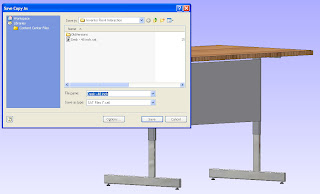
    Export out of Inventor using AEC Exchange option Save As DWG Solids (figure 22).


    figure 22
     Start AutoCAD Application
    In AutoCAD the geometry comes in as a block all on layer "0" (figure 23)


    figure 23
     Create new layers for each discrete material (figure 24).This can be
    preset in a template.
    figure 24
     Explode or refedit the block (figure 25).


    figure 25
     Assign parts to different layers (figure 26).


    figure 26
     Save the File
     In the Revit Family Editor start with the appropriate template, in
    this case we will use the furniture family template furniture.rft
    (figure 27).


    figure 27
    Companies can create their own family templates with manufacturer
    parameters (model numbers, names, cost, etc.) and materials already.
    In the Revit Family Editor use the Import/Link CAD formats to browse
    to and import the modified dwg with geometry assigned to layers
    (figure 28).


    figure 28
     In the Revit Family Editor's Object Styles, materials can be
    assigned to the imported symbols "layers" (figure 29).


    figure 29
     As we have seen when creating families from scratch, or from SAT
    files, we can then assign identity, design and engineering data as
    parameters in the family.
     We also have the same limitation as imported SAT geometry that we
    cannot fully explode nor constrain/flex the imported dwg geometry by
    dimensions.
     Finally, like creating geometry from scratch or SAT import, we save
    and name the file (.rfa), Load it into Projects (.rvt) from the Family
    Editor or from Project itself (Load from Library).Then place as a
    component where needed.
    This article did not go into detail about creating MEP products. These
    would be imported into the Revit MEP Family Editor where duct,
    electrical and piping connectors can be added. I hope to create a
    follow up article covering this.